Showing posts with label Mikrotik. Show all posts

May 2, 2013

Setting up a MikroTik Router as a HotSpot

Basic Setup

Once an IP address is assigned, use Winbox (download from the first time setup page) to do the remainder of the setup.
  • Setup the hotspot as follows (this info is based on http://khmercomputertrick.blogspot.com/2013/03/how-to-setup-your-own-hotspot-with.html
    • Verify that the routerboard DNS settings are correct - click on IP -> DNS and then Settings - if the default values are not correct, update them to reflect the current network. 
    • Add the hotspot service to ether2 (or any other ether port - just replace references to ether2 with whatever ethernet port you are using below) by going IP -> Hotspot and then clicking Hotspot Setup:
 
    • Select ether2 from the drop down and click Next.
    • Pick a suitable IP range to use (192.168.182.1/24 is the default used on HIBs, so use that)

    • Click Next for the "Address Pool of Network"
    • Click Next for the "Certificate" - leave at "none"

    • Ignore the SMTP server setting, and accept the default for the DNS server setting, and leave the DNS name blank.
    • On the next dialog, create a password for the "admin" user - this will allow you to login to the hotspot with this username/password without having to use the RADIUS server - this is useful to verify basic operation before going any further.
  • At this point the basic hotspot should be up and running. Connect a laptop to the ether2 port, and verify that you get an IP address from the range 192.168.182.2 - 192.168.182.254. Try to access the internet using a web browser, and you should get the default MikroTik splash page. You can enter the admin username / password you created above in order to get access to the internet. (if the status / logout dialog does not popup, you can logout using http://192.168.182.1/logout)

Adding RADIUS support to authenticate against SIMPLer

  • Again using winbox, configure RADIUS support as follows:
    • In the hotspot profiles (IP -> HotSpot -> Server Profiles), double click the hotspot you created (should probably be hsprof1)
    • In the Login tab, deselect Cookie and select CHAP and PAP:

    • In the RADIUS tab, select "Use RADIUS", and click OK:

    • On the left colum, click Radius, and then the red + to add a new RADIUS server. On the dialog, click hotspot, and enter the IP address of the RADIUS server and the secret (the default, which you can get from the hotspot setup in SIMPLer is az0s3cr3t):

    • If you want to allow access to certain sites without authentication (e.g. payment gateways, etc), you can add them to IP -> HotSpot -> Walled Garden. For basic setup this should not be necessary.
    • Set the clock on the routerboard by going to System -> NTP Client, click "Enabled", set the Mode to unicast and the server to "pool.ntp.org":

    • Set the system identity to be the hotspot name as follows: Go to System -> Identity and enter the full hotspot name (for example demowisp_demowisp_hs5 is the one I am using):

    • At this point you should be able to login using a token from the selected hotspot. You can verify which users are logged in using IP -> Hotspot -> Active in winbox

Updating the login splash page


The login (and logout) splash pages can be updated as wished. However in order to allow customers to purchase a token using the operator's payment gateway, a link to the SIMPLer captive portal purchase form must be added. The format of the link is as follows:

https://xyz.azotel.com/hotspot/register.pl?hs_name=hotspot_name

Where xyz and hotspot_name are replaced with the relevant equivalents for the operator.

To get the html code for the current login page, click on Files in winbox, and go to hotspot/login.html:


You can just drag'n'drop this file to your desktop, update it, and then drag it back into the Files dialog. Or, if you wish, you can copy the file to your PC using ssh/ftp. The ssh command to copy it is as follows:

    scp admin@<ip of mikrotik>:/hotspot/login.html login.html

To copy it back, use
   
    scp login.html admin@<ip of mikrotik>:/hotspot/login.html

You can also drag'n'drop graphics to the hotspot/img directory to be used on the login page.

Mar 28, 2013

How to Connect your Home Network to xDSL Line with Mikrotik

You have your Home DSL modem installed, and want to have a secure connection to the Internet for your home network. For that, you have to install MikroTik router between the DSL modem and your home network:
Adsl.jpg
Follow the steps below to connect your home network to xDSL line:
  • Make your MikroTik router with two Ethernet NICs, one for the Home DSL modem, one for your home network. See instructions in the Basic Setup Guide!
  • When installing, make sure you install the dhcp software package, if your xDSL service provider uses DHCP to hand out IP configuration, and ppp package, if your service provider uses PPPoE for authentication and IP configuration.
  • Make sure both interfaces are enabled, for example:
/interface enable ether1,ether2
  • If your service provider uses DHCP for IP configuration, add DHCP client on the external (xDSL) interface to receive IP configuration form your service provider:
/ip dhcp-client add interface=ether1 disabled=no
  • Check, if you have received IP configuration using print detail, for example:
[admin@MikroTik] ip dhcp-client> print detail     
Flags: X - disabled, I - invalid 
 0   interface=eth1-adsl add-default-route=yes use-peer-dns=yes 
     use-peer-ntp=yes status=bound address=81.198.55.240/22 
     gateway=81.198.52.1 dhcp-server=81.198.232.1 primary-dns=80.232.169.11 
     secondary-dns=195.122.1.59 expires-after=5h5m46s 
  • If your service provider uses PPPoE for authentication and IP configuration, add PPPoE client to dial out to the service providers PPPoE server and receive IP configuration:
/ interface pppoe-client 
add interface=ether1 user="mtrouter@adsl.com" password="bunny" \
add-default-route=yes use-peer-dns=yes disabled=no
  • Check if you have received IP configuration:
[admin@MikroTik] interface pppoe-client> monitor pppoe-out1 
        status: "connected"
        uptime: 1m17s
     idle-time: 0s
      encoding: "MPPE128 stateless"
  service-name: "home_dsl"
       ac-name: "Telco_DSL"
        ac-mac: 00:0C:42:05:03:99
           mtu: 1480
           mru: 1480
  • Add your private network address to ether2 interface, for example:
/ip address add address=192.168.0.1/24 interface=ether2
  • Configure masquerading for your local network:
/ip firewall nat add chain=srcnat src-address=192.168.0.0/24 action=masquerade
  • Configure firewall to protect your router:
/ ip firewall filter
add chain=input connection-state=established comment="Accept established connections"
add chain=input connection-state=related comment="Accept related connections"
add chain=input connection-state=invalid action=drop comment="Drop invalid connections" 
add chain=input protocol=udp action=accept comment="UDP" disabled=no 
add chain=input protocol=icmp limit=50/5s,2 comment="Allow limited pings" 
add chain=input protocol=icmp action=drop comment="Drop excess pings" 
add chain=input in-interface=ether2 src-address=192.168.0.0/24 comment="From our LAN" action=accept
add chain=input action=log log-prefix="DROP INPUT" comment="Log everything else"
add chain=input action=drop comment="Drop everything else"
  • (Optional) Run DHCP Setup to configure DHCP server to hand out IP configuration on your home network:
/ip dhcp-server setup
  • (Optional) Enable local DNS cache to be used when resolving DNS requests from home computers:
/ip dns set allow-remote-requests=yes
That's it! You can access the Internet from your home network!

Basic Internet Sharing with Bandwidth Limiting -- Mikrotik

This tutorial explains how to configure a router to share a single Internet connection (WAN) among multiple local computers (LAN) using NAT.

First we will configure interface that is connected to WAN.
/ ip address add address=192.168.1.20/24 network=192.168.1.0 broadcast=192.168.1.255 interface=ether2

Now one interface is configured and connected to WAN (with ip 192.168.1.20/24). Now we will configure second interface for our Local Network.
/ ip address add address=192.168.0.1/24 network=192.168.0.0 broadcast=192.168.0.255 interface=ether1

Now we will configure DHCP using WinBOX, download Winbox from http://www.mikrotik.com and login to you MT Router. Then goto IP > DHCP-Server, now press Setup Button, then you will see a similar window as shown below. Just select the interface that you have configured for your Local Network (as in our example it is ether1), now just press Next till the end of setup.

Dhcp-1.JPG

Now we will configure DNS for our local network. Goto IP > DNS, press Settings button then add you Primary and Secondary DNS Server IP as provided by your Internet Service Provider. Also make sure that you select "Allow Remote Requests", so that you can give your MT Router's IP as a DNS Server to your Clients. Then Apply and OK.

Dns.JPG

Now we will configure NATing for our Local Network. Goto IP > Firewall, goto NAT table press the plus sign which will allow you to add new firewall rules. Select chain=srcnat, then set Src. Address=192.168.0.0/24 (ip range of your local network), then select Out.Interface=ether2 (interface connected WAN), as shown below.

Firewall-1.JPG

Now goto Action Tab in the same window, then select Action=Masquerade, then Apply and OK.

Firewall-2.JPG

Now we will setup Bandwidth restriction (10kbps per IP in 192.168.0.0/24 range). Goto Queues, then goto Queue Types, then press the plus sign to add a custom Queue Type. In the name field enter your desired name, select kind=pcq. As shown below.

Bandwidth-1.JPG
Now goto Settings Tab in the same window, and enter the Rate to 10000 (i.e equal to 10kbps), also select Dst. Address, as shown below.

Bandwidth-2.JPG

Now for Upload limit repeat the same procedure to create another Queue Type name it something different and in the Settings Tab instead of selecting Dst. Address this time select Src. Address. Apply and OK

Now in the Queues window goto Simple Queues Tab, and add a new simple queue by pressing plus sign. Enter your desired name, then add a Target Address=192.168.0.0/24 the IP Range of your local network.

Simple-queue-1.JPG
Now goto Advanced Tab in the same window and in Queue Type in the Target Upload select the Queue Type that we created before for upload restriction purpose, do the same for Target Download. As shown below. Press Apply and OK.

Simple-queue-2.JPG

As per the steps shown and performed, you should now have an up and running MT Router, that will serve Internet Service to local network with IP Range 192.168.0.0/24 that will be given by the DHCP Server.

Mar 13, 2013

How to Connect two Mikrotik SXT-5D's In Bridge Mode

Things covered in this how to:
  • Connecting Two Mikrotik RouterBoard SXT-5D devices together in Bridge Mode
  • Upgrading your SXT’s to the Latest Version of RouterOS
  • Doing a Bandwidth Test Between two RouterBoard SXT-5D’s

If you're relatively new to the Mikrotik world my recommendation would be to setup the SXT’s so that they’re both powered on and plugged into the same switch as shown in the photo below.


By default all RouterBoard products come configured with the IP address of the ethernet port set to 192.168.88.1

Connecting for the First Time

There are several ways to get connected to the RouterBoard to start configuring it.

The first and simplest way is to connect using Winbox through the MacAddress connect feature. If you don’t have Winbox on your machine you can download WinBox from here.

With everything plugged into the same switch...open Winbox.

Admin should be in the Username field and the Password field should be blank.

Click the Elipsis button next to the “Connect To:" field. You should see both SXT’s in the dropdown list.


Before I continue, it’s worth mentioning you could add another IP address to your network adapter on the computer you're working on (e.g. 192.168.88.10). You could then put 192.168.88.1 in the “Connect to:” field and you would get connected. The reason I recommend the above way is because it’s not exactly necessary and you’re probably going to be changing the addresses on the SXT’s to match your network anyway.

Click on the MAC address of the first SXT listed (It’s important you click the MAC address - if you click the IP address....you won’t get connected unless you're on the same network.)

Once you login, you’ll see a “RouterOS Default Configuration” screen. Click OK.

With the new WinBox window open....go back and open the WinBox app again and connect to the other SXT - if you're not sure which is which, look at the MAC address at the top of WinBox that’s already open.

Now that you’re WinBox’d into both SXT’s the fun begins!


Getting organized with System Identities


The first configuration change you’ll want to make is to set the “System Identities” so you don’t get confused as to which radio you're working on. In the photo above I have an SXT on the left and one on the right.
  • Click on the System button on the left then Identity
  • Changed the name to something useful - In my case we’ll do SXT Left and SXT Right.
  • Make the change to both radios.

Upgrading RouterOS

At the top of the WinBox screen you’ll see the current version for RouterOS that’s being used. To get the best performance (and to match the instructions below) you really want the latest version. As of this writing that version is 5.1 and you can download it by visiting Mikrotik’s Download page or by clicking here.

Once the file has downloaded, open folder the file was downloaded to, right click on it and Select Copy.

Then do the following to each SXT:
  • Click the Files button on the left
  • Click the Clipboard icon at the top of the FileList window


The file will start to upload. If it doesn’t...go back to where the file download, right click and Copy the file to the system clipboard.


Once it’s done....Click the System button then Reboot.

You should hear a double beep in less than a minute. The double beep lets you know the board is are ready to go.

NOTE: Be sure not to disconnect the power while the boards are upgrading !


Upgrading the Firmware


Log back into both SXTs using WinBox then do the following to upgrade the system firmware.
  • Click the New Terminal button on the left.
  • (Tip: If you want to see what version you’re currently using type system routerboard print)
  • Type system routerboard upgrade
  • Enter Y to confirm you want to upgrade.
  • After upgrading reboot by using the buttons on the left (System > Reboot) or by typing sys reboot then Y to reboot.


Making the Wireless Connection


Now that your SXT’s have the latest and greatest OS and firmware its time to connect them wirelessly.

With a WinBox window open for each device:
  • Click the Wireless button on the top left
  • You’ll notice interface “wlan1” is greyed out or dimmed - this means it’s currently disabled.
  • Right Click on the “wlan1” interface and click Enable in the drop down menu or click the Blue check button on the menu bar. You should see the the interface change to enabled.

We’re going to make the left SXT our “AccessPoint” and the right SXT our “client”.

Note there are a couple settings that you may want to change to something different once you’ve got everything setup. For example you may want to change the SSID to “MyAwesomeBackhaul”....it’s not necessary to get things connected so if this is your first time....don’t change anything unless I mention it (you could boink your link and be frustrated and throw your coffee cup and that wouldn’t be cool).

Do the following on the SXT you’ve decided to be the Access Point. In our case it’s the Left SXT:

AccessPoint Configuration
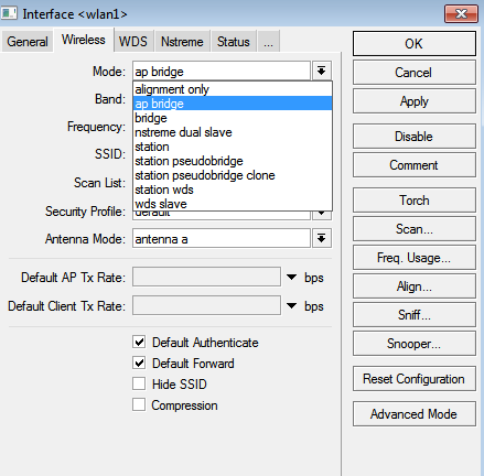
  • Double click on Wlan1.
  • Click the Wireless tab at the top
  • Click the Mode dropdown menu and change it to “Bridge”
  • Click the Band dropdown menu and change it to “5Ghz-only-N”
  • Click the Wireless Protocol dropdown and change it to “NV2”
  • Click the HT tab at the top
  • Select all 4 HT chain options
  • Press the Apply button on the top right.

Client Configuration


You should already have WinBox open and connected to the client or “Right SXT”. (If you jumped ahead....the picture at the beginning shows an SXT on the left and one on the right.)

Now, without making any configuration changes, you should be able to see the AP when doing a scan. Lets go ahead an do that and use the connect button so that we’re sure the SSID’s match.
  • Double click on Wlan1
  • Click the Scan button on the right.
  • The AP should show up, if it doesn’t something isn’t right....Assuming it does, click on the SSID shown in the list and click the Connect Button then Close


By using the Scan and Connect method above, you’ve set the SSID on the client side to match the AP exactly. There are still several things to be changed before they actually connect though.

You should be back at the wireless tab:
  • Click the Mode dropdown menu and change it to “Station Bridge”
  • Click the Band dropdown menu and change it to “5Ghz-only-N”
  • Click the Wireless Protocol dropdown and change it to “Any"
  • Click the HT tab at the top
  • Select all 4 HT chain options


Press the Apply button on the top right.

You should see a “R” next to the wlan Interface in the Wireless Tables window now. This means the client is registered and connected!


If you’re not getting a registration between the two devices or you're having trouble with any of the above steps...head over to the forum and post your question - We’re there to help!

 Setting up the Bridge

To setup the SXT to bridge network traffic do the following to each SXT:

  • Click the Bridge button on the left
  • Click the Plus button on the menu bar

  • Click the STP tab at the top
  • Change the “Protocol Mode:” to RSTP
  • Click OK


Back at the Bridge window:
  • Click the Ports tab at the top
  • Click the Plus button on the menu bar
  • What defaults in the “New Bridge Port” window is what you want, so click OK. This adds Ether1 to the bridge
  • Click the Plus button on the menu bar again.
  • Click the “Interface” drop down menu and select Wlan1
  • Click Ok
Your Bridge window should look similar to this:


Note: As soon as you finish adding the last bridge your going to get disconnected from one of the SXTs. To get reconnected you’ll need to unplug it from the network switch. They’re still connected wirelessly - Just open WinBox and use the MAC address tool to connect.

Bandwidth Test Between Two Mikrotik SXT-5Ds

I’m not going to cover connecting networks between two SXTs - may be in another post - instead, we’ll make a few changes that will allow us to do a quick bandwidth test. These changes should get you on your way to connecting through the devices as well

First Change the IP address on our client bridge (right SXT) to something else besides 192.168.88.1.

  • Click the IP button on the left then Addresses
  • Double click on the default address - 192.168.88.1
  • Change it to 192.168.88.2 (make sure to leave the /24 in there)
  • Click OK


You should now be able to do a bandwidth test.
  • WinBox Into the Access Point SXT (Still using the MAC Address Tool)
  • Click the Tools button on the left then Bandwidth Test
  • Change the “Test To:” field to the address of the client - 192.168.88.2
  • Click the “User” field and enter admin for the username
  • Click the Start button


Now if you were to test TCP traffic at this point - The results wouldn't be as impressive. This is because you’re relying on the SXT’s to both process and create traffic. This causes a hit to the processor that slows everything down.


Testing through an SXT to a RouterBoard 800 is a different story. Note that you would probably see more...but the SXT only has a 100MB ethernet port.


Getting the most out of your SXT

Now if you really want to push the SXT’s to get the maximum throughput there are a few things to change.

If you haven’t already, you might get as much separation as possible from one SXT to another. In all of the tests below - the SXTs are about 30 feet (10 meters) from each other. This will help their performance.

The first thing we’re going to change is the TX power. With the radios still so close together the signals will to be too high and you’re not going to get the best results.

Do the following to both SXTs:

  • Double click on the Wlan1 in the Wireless Tables
  • Click the Advance Mode button at the bottom right (If you’re already in advance mode - you’ll see a Simple Mode button instead - don’t click it just go to the next step.)
  • Click the TX Power tab
  • Click the TX Power Mode list and select All rates fixed
  • Now here is where it gets tricky....if the radios are just a few feet away then you shouldn’t have any problems setting the TX Power to 0. The goal here is to lower the TX power until you get the signals to be somewhere between -45 and -60 dB on both sides.


IMPORTANT: Make sure that you change the TX Power settings back to defaults before you unplug your SXT’s and try to deploy them in the field. Otherwise...you’ll be sad.

Now for the additional changes to max everything out. There are a few changes here that have the potential to increase latency, AMPDU Priorities being one of them. I’m not suggesting that you leave these settings in the real world...I’m just showing what is possible.

If you have any questions about these settings, again, hop over to the forum and ask away!

Make the following changes on both sides *beginning with the client first*.

  • Double click on the Wlan1 interface in the Wireless Tables
  • Click the Advance Mode button at the bottom right (If you’re already in advance mode - you’ll see a Simple Mode button instead - don’t click it just go to the next step.)
  • Click the HT tab
  • Set “HT Guard Interval” to long
  • Click the “HT Extension Channel” list and select Above Control
  • Select all 7 Options under “HT AMPDU Priorities”


With the new settings our UDP Bandwidth test looks like this.


And testing Both ways

How to Setup Your Own Hotspot with MIKROTIK routers

1. First we need to define the first port for WAN connection so the router will connect to the internet via another router with DHCP.
In winbox click IP > DHCP Client and Add DHCP Client to port ether1
2. Let's add the hotspot service to wlan Click IP > HotSpot and the hotspot Setup box, choose wlan1 as hotspot interface. You can accept default values but choose none for certificate. Leave the IP as it is (10.5.50.x). If you change this IP, the LOGIN and LOGOUT links will not work on your splash page.

3. The router should be placed in ap bridge mode.
Click interface, double click wlan1, click Mode: and select ap bridge
And make sure the frequency is set to 2.4 b/G.
4. You need to add our radius server as authentication and accounting server.
In the hotspot profiles (IP > HotSpot > Profiles) choose your hotspot profile and click the radius tab, check allow radius. Then click the login tab and de-select cookie, allow http pap and chap.

5. You need to define our radius server. Click Radius and the + sign to add our radius server.
Click Services > Hotspot, enter radius address: Radius.hotspotsystem.com, Secret: hotsys123
Check the box next to hotspot

6. You need to add the secondary radius server. Click Radius and the + sign.
Click Services > Hotspot, enter radius Address: radius2.hotspotsystem.com, Secret: hotsys123
Check the box next to hotspot
7. We have to allow certain sites and servers for non authenticated users otherwise they can't buy access.
In the section IP > HotSpot > Walled Garden, click on + sign and add the following domains to Dst. Host one by one:
*.hotspotsystem.com
*.worldpay.com
*.paypal.com
*.paypalobjects.com
*.paypal-metrics.com
*.altfarm.mediaplex.com
*.akamaiedge.net
paypal.112.2O7.net
*.moneybookers.com
*.adyen.com *.directebanking.com
*.paysafecard.com
betalen.rabobank.nl
ideal.ing.nl
internetbankieren.frieslandbank.nl
ideal.abnamro.nl
ideal.snsreaal.nl
ideal.triodos-onlinebanking.nl

For Hotspot FREE SOCIAL locations: you must add 'www.apple.com' too!
Then in the section IP > HotSpot > Walled Garden > IP List add the following IPs to Dst. Address one by one (if your Mikrotik doesn't allow netmask values (.0/24) you can skip the netmask value):
194.149.46.0/24
198.241.128.0/17
66.211.128.0/17
216.113.128.0/17
70.42.128.0/17
128.242.125.0/24
216.52.17.0/24
62.249.232.74
155.136.68.77
66.4.128.0/17
66.211.128.0/17
66.235.128.0/17
88.221.136.146
195.228.254.149
195.228.254.152
203.211.140.157
203.211.150.204
82.199.90.136/29
82.199.90.160/27
91.212.42.0/24
8. You need to syncronize the router's time with our server.
Click on System > NTP Client. Enter primary and secondary NTP servers. To find NTP servers, go to http://www.pool.ntp.org/ and select the location's continent on the right side of the page. You'll find NTP servers there.
Be sure to leave TimeZoneName: manual, and TimeZone: 00:00 in System > Clock. (Don't set your own timezone, because the router has to show the GMT time!)

9. You need to change the router's NASID. The NASID setting in the Mikrotik is located under System > Identity. Default is 'MikroTik'.
Change this the following way: OPERATORUSERNAME_LOCATIONNUMBER
Example: Operator Username is 'globalhotspot', Location ID: '2', then NASID should be: 'globalhotspot_2'
NOTE: In case you are installing multiple routers in the same location, you should use different NAS IDs. For the second routers you need to add '_wds_1' to the NAS Id, for the third router '_wds_2', etc. So for example if you want to install the second router in location 3, the NASID should be set to 'globalhotspot_3_wds_1'.

10. You have to customize Mikrotik's built-in login page. On the side menu go to Files, and find the login.html file under the 'hotspot' directory. Double click on the file and choose Backup.
Open a simple text editor like notepad and copy and paste the following to the editor:

Save it as login.html to your Desktop.
Drag and drop this login.html to your "hotspot" directory in the Winbox program.
If you wish to use FTP you can FTP to your mikrotik router with the admin userid and password and replace the file there under the 'hotspot' directory.
If you don't wish to redirect users to our nice splash page you can continue to use the router's built-in login page but in this case it is important to add a link to the internal page where your users can buy access or activate their prepaid cards. Click here for more information.

10/b. In case you are using Hotspot FREE SOCIAL service, you also need to edit logout.html template. You need to use the same content as for the login.html (code above).

11. You have to set the Login/Logout URL IP addresses in the Control Center. Log in to the Control Center with your Operator Username and password and go to Manage > Locations. Click on the location, then click on Modify Hotspot Data & Settings. In Splash Page Settings modify the Internal Login/Logout URL Set to Mikrotik. Make sure that 'Display Login Box on Main Splash Page' option is CHECKED.

12. Extend the shared-users limit in your hotspot profile.
Sub-menu: /ip hotspot user profile
or go to IP > Hotspot > User Profiles > default > Shared-Users
Change shared-users to 5.

13. As the last step you have to add hourly checking for up status for the Router Alert feature.
Go to System > Scheduler and add a new task by pressing the plus sign.
Name: up
Interval: 01:00:00
On Event:


Policy: enable all
Press Apply and OK.
That's all. You can setup hotspot service even on a wired connection. In this case you have to choose an ethernet port instead of wlan or you can setup hotspot on both ports.
If you have successfully setup your mikrotik router you have to see a login window when connecting via wireless. You can log in with username admin, blank password.

How to set up OpenVPN on router: Mikrotik RouterOS

IMPORTANT: Don't setup your Mikrotik RouterOS remotely. You have to be connected via the LAN interface, otherwise you will cut the connection (access to the router) and you will not be able to access it remotely any more.
  1. Update Router OS on your Mikrotik router to latest version (at least version v5.8)
  2. Connect to your Mikrotik router via WinBox.
  3. Setup the DNS servers manually to Google DNS: IP -> DNS -> Settings -> Servers
    • 8.8.8.8
    • 8.8.4.4
  4. Write down the default gateway IP address of your Internet provider (ISP) and remove the default-route (Dst. Address = 0.0.0.0/0 routed via your ISP GW) from the routing table. If you don't use DHCP Client please follow the STEP 5.
  5. Go to IP -> DHCP Client and disable the "Add Default Route" option.
  6. Your routing table should not contain any default route now. See the screen bellow.
  7. Add new static route to your routing table. Dst. address is an IP address of the VPN server you want connect to. Gateway is the default gateway IP address of your Internet provider (ISP). You should have the IP written down since STEP 1.
  8. Setup the OVPN client according to the screens bellow. Status should appear as connected once you click Apply.
  9. Please check your interfaces and routing table again. The correct configuration should look similar to the screen bellow.
  10. Now you should be able to ping for example google.com. If all works well, then you can setup NAT masquerade of your LAN network so all devices behind the Mikrotik Router will use the VPN connection.

Twitter Delicious Facebook Digg Stumbleupon Favorites More

 
Design by Computer Tricks and Tips