The CLI
Winbox is a fantastic program. It is extremely powerful, and is a
very quick way to edit or monitor RouterOS routers. It is, however, also
a fairly poor tool for sharing configuration across the Internet. You
can take screenshots, but screenshots are large files and might not
display right. Depending on where they are hosted they might not stay
around for very long as the file host takes them down. Most importantly
there simply isn't enough space in most Winbox dialogs to show all the
relevant information in one small area. Firewall rules in Winbox, for
example, consist of many tabs. To adequately show all properties of a
rule - when troubleshooting it, for example - you'd have to share one
screenshot for each tab. CLI output, on the other hand, shows all that
information in just one line. Text is also universal - everything can
display text. You can also copy and paste text, which means it's much
easier to apply a firewall rule that someone gave you as a CLI command
than it is to click through all the tabs in Winbox and set all the
fields accordingly.
The CLI may initially seem somewhat daunting but actuallt
organized very well. There are only 9 different commands that really are
important for basic configuration tasks.
Structure
The RouterOS CLI mirrors the GUI (or rather, the GUI mirrors the
CLI). The configuration is divided into menu structures, several levels
deep. For example, IP services are configured under "/ip" with
subsections for the specific related tasks: ARP is configured under "/ip
arp", the firewall is configured under "/ip firewall", and so on.
All commands can be prefaced with an absolute or relative
reference to the context in which the command is to be executed. If no
context is given, the current context is used. Below three examples:
[admin@Example-Router] /ip address> print
This "print" command will be executed in the "/ip address" context, and will therefore print all configured IP addresses.
[admin@Example-Router] /ip address> /ip arp print
This "print" command is prefaced with an absolute context of "/ip
arp" and will be executed in that context, and will therefore print all
ARP entries the router knows about.
[admin@Example-Router] /ip address> .. arp print
This "print" command is prefaced with a relative context of ".. arp".
The current context is "/ip address", ".." goes one level up to "/ip",
and "arp" goes into "/ip arp". Therefore the command will print all ARP
entries the router knows about.
The <tab> key triggers auto completion, if the current word
cannot be auto completed because several possibilities exist pressing
<tab> a second time shows all possible completions. '?' shows help
for existing options at the current position of the command.
Commands are syntax highlighted - command words are pink, items
are cyan, and parameter names are green. When syntax highlighting stops
the OS cannot parse the command, and the command will not execute
properly.
Commands can be abbreviated when they are unambiguous. For
example, "/ip address add address=1.1.1.2/24 interface=WAN" can - at an
extreme - be abbreviated as "/ip ad a a=1.1.1/24 i=WAN".
Parameters are passed as key/value pairs separated by '=' signs.
In the example above the address parameter is set to 1.1.1.2/24, and the
interface parameter is set to the interface named "WAN".
There are two different types of configuration: one simply exists
and has parameters set on it (e.g., the internal DNS server can be
turned on or off), others are items added to a section as instances in a
list of items in the same context (e.g., VLAN interfaces that can be
freely created, or IP addresses assigned to interfaces).
For purposes of displaying commands it is possible to split one
very long line over several lines. This is indicated by a backslash at
the end of a line - the next line continues that line. Here an example:
[admin@Example-Router] > /ip address add \
   interface=outside \
   address=1.1.1.2/30
This is used in this tutorial to wrap long configuration commands.
Basic commands
The same basic commands are used to configure all aspects of the OS.
Commands exist to look at configuration, to add configuration, to remove
configuration, and to edit existing configuration.
print
The "print" command prints configuration items in the current
context. It has several qualifiers that can be used to change what
information is output, and how it is formatted. The most important
qualifier is "print detail". "print detail"'" shows all properties of an
item, ensures that everything gets printed ("print" by default shows
everything neatly organized into rows and columns of a table, but may
truncate strings to make them all fit on the screen), and outputs
everything as neat key/value pairs. This is especially valuable when
sharing information on the forums when asking for help.
[admin@Example-Router] > /ip arp print
Flags: X - disabled, I - invalid, H - DHCP, D - dynamic
 #   ADDRESS         MAC-ADDRESS       INTERFACE
 0 D 1.1.1.2         00:0B:BF:93:68:1B outside
[admin@Example-Router] >

[admin@Example-Router] > /ip arp print detail
Flags: X - disabled, I - invalid, H - DHCP, D - dynamic
 0 D address=1.1.1.2 mac-address=00:0B:BF:93:68:1B interface=outside
[admin@Example-Router] >
The print command in its first column returns an item number. In
subsequent commands the item number can be used to refer to that item.
export
The "export" command prints the configuration applied in a format
that can be copied and pasted to duplicate the same configuration on
another router. The "export" command will return the configuration of
the current section, and all child sections. For example, the "/ip
firewall" context has child contexts for NAT and filters. "/ip firewall
export" would return those child section configurations as well.
remove
The "remove" command deletes an item from a list of configuration
items. It refers to an item number, or the result of a "find" command.
[admin@Example-Router] > /ip address print
Flags: X - disabled, I - invalid, D - dynamic
 #   ADDRESS            NETWORK         BROADCAST       INTERFACE
 0   10.1.0.1/24        10.1.0.0        10.1.0.255      inside
 1   1.1.1.2/29         1.1.1.0         1.1.1.7         outside
 2   10.2.0.1/24        10.2.0.0        10.2.0.255      dmz
[admin@Example-Router] > /ip address remove 2
[admin@Example-Router] > /ip address print
Flags: X - disabled, I - invalid, D - dynamic
 #   ADDRESS            NETWORK         BROADCAST       INTERFACE
 0   10.1.0.1/24        10.1.0.0        10.1.0.255      inside
 1   1.1.1.2/29         1.1.1.0         1.1.1.7         outside
[admin@Example-Router] >
add
The "add" command adds an item to a list of configuration items. It
will ask for all parameters that are required but not specified.
[admin@Example-Router] > /ip address print
Flags: X - disabled, I - invalid, D - dynamic
 #   ADDRESS            NETWORK         BROADCAST       INTERFACE
 0   10.1.0.1/24        10.1.0.0        10.1.0.255      inside
 1   1.1.1.2/29         1.1.1.0         1.1.1.7         outside
[admin@Example-Router] > /ip address add address=10.2.0.1/24 interface=dmz
[admin@Example-Router] > /ip address print
Flags: X - disabled, I - invalid, D - dynamic
 #   ADDRESS            NETWORK         BROADCAST       INTERFACE
 0   10.1.0.1/24        10.1.0.0        10.1.0.255      inside
 1   1.1.1.2/29         1.1.1.0         1.1.1.7         outside
 2   10.2.0.1/24        10.2.0.0        10.2.0.255      dmz
[admin@Example-Router] >
set
The "set" command edits parameters of an existing item.
[admin@Example-Router] > /ip address print
Flags: X - disabled, I - invalid, D - dynamic
 #   ADDRESS            NETWORK         BROADCAST       INTERFACE
 0   10.1.0.1/24        10.1.0.0        10.1.0.255      inside
 1   1.1.1.2/29         1.1.1.0         1.1.1.7         outside
 2   10.2.0.1/24        10.2.0.0        10.2.0.255      dmz
[admin@Example-Router] > /ip address set 2 interface=inside
[admin@Example-Router] > /ip address print
Flags: X - disabled, I - invalid, D - dynamic
 #   ADDRESS            NETWORK         BROADCAST       INTERFACE
 0   10.1.0.1/24        10.1.0.0        10.1.0.255      inside
 1   1.1.1.2/29         1.1.1.0         1.1.1.7         outside
 2   10.2.0.1/24        10.2.0.0        10.2.0.255      inside
[admin@Example-Router] > /ip address set 2 interface=dmz
[admin@Example-Router] > /ip address print
Flags: X - disabled, I - invalid, D - dynamic
 #   ADDRESS            NETWORK         BROADCAST       INTERFACE
 0   10.1.0.1/24        10.1.0.0        10.1.0.255      inside
 1   1.1.1.2/29         1.1.1.0         1.1.1.7         outside
 2   10.2.0.1/24        10.2.0.0        10.2.0.255      dmz
[admin@Example-Router] >
disable
The "disable" command disables a configuration item rendering it inoperative, but leaving it in the configuration.
[admin@Example-Router] > /ip address print
Flags: X - disabled, I - invalid, D - dynamic
 #   ADDRESS            NETWORK         BROADCAST       INTERFACE
 0   10.1.0.1/24        10.1.0.0        10.1.0.255      inside
 1   1.1.1.2/29         1.1.1.0         1.1.1.7         outside
 2   10.2.0.1/24        10.2.0.0        10.2.0.255      dmz
[admin@Example-Router] > /ip address disable 2
[admin@Example-Router] > /ip address print
Flags: X - disabled, I - invalid, D - dynamic
 #   ADDRESS            NETWORK         BROADCAST       INTERFACE
 0   10.1.0.1/24        10.1.0.0        10.1.0.255      inside
 1   1.1.1.2/29         1.1.1.0         1.1.1.7         outside
 2 X 10.2.0.1/24        10.2.0.0        10.2.0.255      dmz
[admin@Example-Router] >
enable
The "enable" command enables a previously disabled item.
[admin@Example-Router] > /ip address print
Flags: X - disabled, I - invalid, D - dynamic
 #   ADDRESS            NETWORK         BROADCAST       INTERFACE
 0   10.1.0.1/24        10.1.0.0        10.1.0.255      inside
 1   1.1.1.2/29         1.1.1.0         1.1.1.7         outside
 2 X 10.2.0.1/24        10.2.0.0        10.2.0.255      dmz
[admin@Example-Router] > /ip address enable 2
[admin@Example-Router] > /ip address print
Flags: X - disabled, I - invalid, D - dynamic
 #   ADDRESS            NETWORK         BROADCAST       INTERFACE
 0   10.1.0.1/24        10.1.0.0        10.1.0.255      inside
 1   1.1.1.2/29         1.1.1.0         1.1.1.7         outside
 2   10.2.0.1/24        10.2.0.0        10.2.0.255      dmz
[admin@Example-Router] >
find
The "find" command returns a set of items that can then be acted on
by other commands. When "find" is executed without any parameters, it
returns all items. When "find" is executed with parameters only items
that match the parameters are returned. The most common matcher is "="
to exactly match a parameter value, it is also possible to match regular
expressions with the "~" operator.
The below enables all IP addresses that exist:
[admin@Example-Router] > /ip address print
Flags: X - disabled, I - invalid, D - dynamic
 #   ADDRESS            NETWORK         BROADCAST       INTERFACE
 0   10.1.0.1/24        10.1.0.0        10.1.0.255      inside
 1   1.1.1.2/29         1.1.1.0         1.1.1.7         outside
 2 X 10.2.0.1/24        10.2.0.0        10.2.0.255      dmz
[admin@Example-Router] > /ip address enable [/ip address find]
[admin@Example-Router] > /ip address print
Flags: X - disabled, I - invalid, D - dynamic
 #   ADDRESS            NETWORK         BROADCAST       INTERFACE
 0   10.1.0.1/24        10.1.0.0        10.1.0.255      inside
 1   1.1.1.2/29         1.1.1.0         1.1.1.7         outside
 2   10.2.0.1/24        10.2.0.0        10.2.0.255      dmz
[admin@Example-Router] >
The below disables all IP addresses that are on interface "dmz":
[admin@Example-Router] > /ip address print
Flags: X - disabled, I - invalid, D - dynamic
 #   ADDRESS            NETWORK         BROADCAST       INTERFACE
 0   10.1.0.1/24        10.1.0.0        10.1.0.255      inside
 1   1.1.1.2/29         1.1.1.0         1.1.1.7         outside
 2   10.2.0.1/24        10.2.0.0        10.2.0.255      dmz
[admin@Example-Router] > /ip address disable [/ip address find interface=dmz]
[admin@Example-Router] > /ip address print
Flags: X - disabled, I - invalid, D - dynamic
 #   ADDRESS            NETWORK         BROADCAST       INTERFACE
 0   10.1.0.1/24        10.1.0.0        10.1.0.255      inside
 1   1.1.1.2/29         1.1.1.0         1.1.1.7         outside
 2 X 10.2.0.1/24        10.2.0.0        10.2.0.255      dmz
[admin@Example-Router] >
The below enables all IP addresses that are on interfaces that start with the letter "d":
[admin@Example-Router] > /ip address print
Flags: X - disabled, I - invalid, D - dynamic
 #   ADDRESS            NETWORK         BROADCAST       INTERFACE
 0   10.1.0.1/24        10.1.0.0        10.1.0.255      inside
 1   1.1.1.2/29         1.1.1.0         1.1.1.7         outside
 2 X 10.2.0.1/24        10.2.0.0        10.2.0.255      dmz
[admin@Example-Router] > /ip address enable [/ip address find interface~"^d"]
[admin@Example-Router] > /ip address print
Flags: X - disabled, I - invalid, D - dynamic
 #   ADDRESS            NETWORK         BROADCAST       INTERFACE
 0   10.1.0.1/24        10.1.0.0        10.1.0.255      inside
 1   1.1.1.2/29         1.1.1.0         1.1.1.7         outside
 2   10.2.0.1/24        10.2.0.0        10.2.0.255      dmz
[admin@Example-Router] >
move
The "move" command moves items in ordered lists where order is
important for flow of execution. Order is especially important for rules
in the IP firewall filter, mangle, and NAT facilities. Items can be
moved by referring to the ID of the item that is being moved, and the ID
of the item the rule should be moved to. The below moves rule number 3
into the place of rule number 0, and all other rules shift down. The
firewall rules shown are non-sensical and only for demonstration of the
"move" command:
[admin@Example-Router] > /ip firewall mangle print where action="mark-routing"
Flags: X - disabled, I - invalid, D - dynamic
 0   chain=prerouting action=mark-routing new-routing-mark="mark-a"
 1   chain=prerouting action=mark-routing new-routing-mark="mark-b"
 2   chain=prerouting action=mark-routing new-routing-mark="mark-c"
 3   chain=prerouting action=mark-routing new-routing-mark="mark-d"
[admin@Example-Router] > /ip firewall mangle move 3 0
[admin@Example-Router] >
[admin@Example-Router] > /ip firewall mangle print where action="mark-routing"
Flags: X - disabled, I - invalid, D - dynamic
 0   chain=prerouting action=mark-routing new-routing-mark="mark-d"
 1   chain=prerouting action=mark-routing new-routing-mark="mark-a"
 2   chain=prerouting action=mark-routing new-routing-mark="mark-b"
 3   chain=prerouting action=mark-routing new-routing-mark="mark-c"
[admin@Example-Router] >
Context
Contexts can also be set for a set of commands by enclosing a set in
braces, saving keystrokes. The below enables all IP addresses:
[admin@Example-Router] > /ip address print
Flags: X - disabled, I - invalid, D - dynamic
 #   ADDRESS            NETWORK         BROADCAST       INTERFACE
 0   10.1.0.1/24        10.1.0.0        10.1.0.255      inside
 1   1.1.1.2/29         1.1.1.0         1.1.1.7         outside
 2 X 10.2.0.1/24        10.2.0.0        10.2.0.255      dmz
[admin@Example-Router] > /ip address { enable [find] };
[admin@Example-Router] > /ip address print
Flags: X - disabled, I - invalid, D - dynamic
 #   ADDRESS            NETWORK         BROADCAST       INTERFACE
 0   10.1.0.1/24        10.1.0.0        10.1.0.255      inside
 1   1.1.1.2/29         1.1.1.0         1.1.1.7         outside
 2   10.2.0.1/24        10.2.0.0        10.2.0.255      dmz
[admin@Example-Router] >
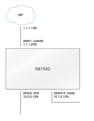
Example network
This tutorial uses an example network to explain configuration. The
router has a public IP address of 1.1.1.2/30 with a default gateway of
1.1.1.1, and port 'ether1' (later renamed to 'outside') is used to
connect to the ISP. Port 'ether2' (later renamed to 'dmz') is a network
that is a true DMZ, this network uses IP address 10.2.0.1/24. Ports
'ether3' through 'ether5' are switched together and all are available
for use on the LAN network, later renamed to 'inside'. This network uses
10.1.0.1/24.
Other SoHo routers refer to unconditional port forwarding to a
LAN machine as a DMZ. In more advanced networks DMZ refers to a third
network other than WAN and LAN, where hosts run services accessible to
the Internet at large. Running this in a different network further
protects the LAN network: hosts in the DMZ are exposed to the Internet
and may be under attach. If breached this doesn't gain the attached
access to the LAN network as a firewall doesn't permit DMZ hosts to
establish new connections to the LAN.
Router interfaces (ports)
Physical interfaces
Different router models have different sets of physical interfaces.
RB1000s have a total of 4 1000Base-TX ports. RB1100s have 10 1000Base-TX
ports (2 groups of 5 ports with a 1Gbps pipe to the CPU per group, each
group has a switch chip for wire speed layer 2 throughput), and 3
100Base-TX ports. RB750Gs have 5 total 1000Base-TX ports with a switch
chip for wire speed layer 2 throughput.
routerboard.com has all the data sheets and specs.
Switch Chip
Some routers have a built in switch chip that can be activated on
physical interfaces to permit wire speed throughput between those
interfaces. Those interfaces will essentially act like a switch would.
By default this is enabled in the SoHo models. While more advanced
configuration is possible most small networks simply need to activate or
deactivate the feature. Within the switch chips interfaces are either
master ports or slave ports. The master port is where all the router
configuration happens (such as the IP address), and the slave ports
refer to the master port. The below configures interfaces ether3,
ether4, and ether5 as slaves to interface ether2:
/interface ethernet
set [find name=ether3] master-port=ether2
set [find name=ether4] master-port=ether2
set [find name=ether5] master-port=ether2
The switch chip is capable for small networks, but can't do advanced VLAN configurations.
Bridging vs routing
Bridging (which is what switches do) is something that switches do a
lot better than routers. This is just a personal opinion, but whenever I
find myself thinking that I should bridge wired interfaces I almost
always end up using a switch instead. One counterexample are wireless
interfaces, which are commonly bridged into wired networks.
Named interfaces
All configuration of interfaces in RouterOS is done against the name of an interface. Names can be arbitrarily set.
It is good practice to make the names informative. A good name
for the interface used to connect to the Internet is 'outside' or 'WAN',
a good name for the the interface used to connect to inside customers
or your home network is 'inside' or 'LAN'. When using the switch chip
the names for the slaved interfaces are unimportant in all but fairly
advanced configurations since any router configuration will be limited
to the master port. It can still make good sense to name the interfaces
after what they connect to.
Example network
In our example network we want ether1 to be named 'outside', ether2
to be named 'dmz', and ether3 - ether5 to be switched with an interface
name of 'inside'.
/interface ethernet
set [find name=ether1] name=outside
set [find name=ether2] name=dmz
set [find name=ether3] name=inside
set [find name=ether4] name=inside-slave master-port=inside
set [find name=ether5] name=inside-slave2 master-port=inside
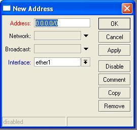
IP addresses
Each interface can carry one or more IP addresses on it. Usually only
one IP address per interface is defined. While viewing IP addresses
shows parameters for the network and broadcast address of the network,
these should usually not be defined manually and will automatically be
added when left out. When adding the IP address the subnet mask is given
in CIDR notation.
[admin@Example-Router] /ip address> print
Flags: X - disabled, I - invalid, D - dynamic
 #   ADDRESS            NETWORK         BROADCAST       INTERFACE
 0   10.1.0.1/24        10.1.0.0        10.1.0.255      inside
[admin@Example-Router] /ip address> add address=1.1.1.2/29 interface=outside
[admin@Example-Router] /ip address> print
Flags: X - disabled, I - invalid, D - dynamic
 #   ADDRESS            NETWORK         BROADCAST       INTERFACE
 0   10.1.0.1/24        10.1.0.0        10.1.0.255      inside
 1   1.1.1.2/29         1.1.1.0         1.1.1.7         outside
[admin@Example-Router] /ip address>
DHCP client
In many small environments the router will receive a dynamic IP
address via DHCP on its WAN interface from the ISP. The DHCP client can
also be used to populate the routing table with a default route via the
ISP, and pull in DNS servers for the router - and the networks behind it
- to use. The DHCP client must be given an interface to run on, as well
as whether to listen to the DHCP options for DNS and a default route.
/ip dhcp-client
add interface=outside add-default-route=yes use-peer-dns=yes
PPPoE client
The other common method for SoHo routers to receive a public IP
address is via PPPoE, which is used in DSL connections. Most DSL modems
can be set into a bridge mode where the modem performs the translation
between the DSL network and regular Ethernet, the router then becomes
the PPPoE client and directly talks to the ISP network through the
modem. PPPoE assigns an IP address to the interface the PPPoE client is
running on, and can also be used to learn about a default route as well
as DNS servers. It is very important to note that the PPPoE client
creates a new logical interface (in the example below it is named
'pppoe-WAN') which now becomes the interface to refer to for WAN
traffic. The 'outside' interface will only be used for the PPPoE
encapsulated traffic, as far as the router is concerned IP traffic will
be leaving the router via the PPPoE client interface.
/interface pppoe-client
add name=pppoe-WAN interface=outside add-default-route=yes use-peer-dns=yes
Example network
In our example network we want the 'outside' interface to have a
static IP address of 1.1.1.2/29, the 'dmz' interface to have a static IP
address of 10.2.0.1/24, and the 'inside' interface to ave a static IP
address of 10.1.0.1/24.
/ip address
add address=1.1.1.2/29 interface=outside
add address=10.2.0.1/24 interface=dmz
add address=10.1.0.1/24 interface=inside
IP routes
Just like on other routing platforms dynamic connected routes are
created for all networks that the router has IP addresses to - after
all, if the router has an IP address in the 10.1.0.1/24 network on the
"inside" interface then it can reach hosts on that network via that
interface. Static routes can be added by defining a destination address
and a gateway. Usually at least one static route is required: a default
route for the router pointing out to the ISP network. RouterOS can of
course also run dynamic routing protocols such as RIP, OSPF, and BGP,
but that is outside the scope of this article.
[admin@Example-Router] > /ip route print
Flags: X - disabled, A - active, D - dynamic,
C - connect, S - static, r - rip, b - bgp, o - ospf, m - mme,
B - blackhole, U - unreachable, P - prohibit
 #      DST-ADDRESS        PREF-SRC        GATEWAY            DISTANCE
 0 ADC  10.1.0.0/24        10.1.0.1        inside             0
 1 ADC  1.1.1.0/29         1.1.1.2         outside            0
[admin@Example-Router] >
While RouterOS will let you configure an IP address within the smae
network on two different routed interfaces it would be very bad to do
so. The router now would think that it can reach the hosts within that
network via either interface, which is unlikely to be the case.
Adding a default route
New static routes can be added as per below. The example shows adding
a default route (a route for destination 0.0.0.0/0) via the ISP gateway
1.1.1.1:
[admin@Example-Router] > /ip route add dst-address=0.0.0.0/0 gateway=1.1.1.1
[admin@Example-Router] > /ip route print
Flags: X - disabled, A - active, D - dynamic,
C - connect, S - static, r - rip, b - bgp, o - ospf, m - mme,
B - blackhole, U - unreachable, P - prohibit
 #      DST-ADDRESS        PREF-SRC        GATEWAY            DISTANCE
 0 A S  0.0.0.0/0                          1.1.1.1            1
 1 ADC  10.1.0.0/24        10.1.0.1        inside             0
 2 ADC  1.1.1.0/29         1.1.1.2         outside            0
[admin@Example-Router] >
It is interesting to note that technically two routes are now
involved for traffic to the Internet: the router looks at the packet and
finds that the default route matches, and that it should send traffic
via 1.1.1.1. It then needs to figure out how to send traffic to 1.1.1.1,
looks at its routing table again, and finds that it can get to 1.1.1.1
via the "outside" interface via the directly connected route for that
network.
Also note that it is not necessary or recommended to add a static
default route if your router receives its WAN IP address via DHCP or
PPPoE. Static default routes should only be used when the public IP
address on the WAN interface is also static.
Example network
In our example network we want the router to use 1.1.1.1 as a default gateway:
/ip route
add dst-address=0.0.0.0/0 gateway=1.1.1.1
DHCP server
DHCP server services consist of three components: the IP pool that
defines the range of IP addresses clients can receive a lease for, the
DHCP server network that defines the parameters clients are passed (such
as gateway IP address and DNS servers), and the DHCP server instance
itself that ties a pool to an interface.
IP Pools
IP pools define the range of IP addresses available for users to
obtain as a DHCP lease. Any IP address in a subnet not covered by the
pool range is available for static use.
IP pools simply consist of a name that they can be referred to
by, as well as a range of IP addresses. The OS will let you set a range
that is out of the bounds of the subnet of the network users will
actually be on, leading to IP addresses unable to reach their default
gateway. Be careful when adjusting ranges to check that the range chosen
is actually covered by the IP network configured on the interface.
To add a pool:
[admin@Example-Router] /ip pool> export
/ip pool
add name=DHCP-Pool-inside ranges=10.1.0.10-10.1.0.100
[admin@Example-Router] /ip pool>
To edit a pool:
[admin@Example-Router] /ip pool> print
# NAME               RANGES
 0 DHCP-Pool-inside  10.1.0.10-10.1.0.100
[admin@Example-Router] /ip pool> set [find name="DHCP-Pool-inside"] ranges=10.1.0.100-10.1.0.200
[admin@Example-Router] /ip pool> print
# NAME               RANGES
 0 DHCP-Pool-inside  10.1.0.100-10.1.0.200
[admin@Example-Router] /ip pool>
DHCP Server Networks
DHCP server networks define parameters (DHCP options) to pass on to
DHCP clients. The minimum set of options include the default gateway and
name servers. The default gateway is usually the IP address of the
router on the network interface, and the name servers usually is as well
- at least as long as the router is configured as a DNS caching
resolver. That is covered in a different section of this document.
To add a DHCP server network:
[admin@Example-Router] /ip dhcp-server network> export
/ip dhcp-server network
add address=10.1.0.0/24 comment=inside dns-server=10.1.0.1 gateway=10.1.0.1
[admin@Example-Router] /ip dhcp-server network>
Note that multiple DNS servers are specified as a comma separated list without spaces.
To edit a DHCP server network:
[admin@Example-Router] /ip dhcp-server network> print
 # ADDRESS            GATEWAY         DNS-SERVER      WINS-SERVER     DOMAIN
 0 ;;; inside
   10.1.0.0/24        10.1.0.1        10.1.0.1
[admin@Example-Router] /ip dhcp-server network> set [find comment="inside"] dns-server=8.8.8.8
[admin@Example-Router] /ip dhcp-server network> print
 # ADDRESS            GATEWAY         DNS-SERVER      WINS-SERVER     DOMAIN
 0 ;;; inside
   10.1.0.0/24        10.1.0.1        8.8.8.8
[admin@Example-Router] /ip dhcp-server network>
DHCP Servers
DHCP server instances cause the DHCP server process in the router to
listen for client requests on the specified interfaces. Each interface
that is to offer DHCP to clients must have a dedicated DHCP server
instance. The instance sets basic parameters such as whether the server
is authoritative and the client lease time, and ties IP pools to
interfaces.
To add a DHCP server instance:
[admin@Example-Router] /ip dhcp-server> export
/ip dhcp-server
add address-pool=DHCP-Pool-inside authoritative=yes bootp-support=static \
   disabled=no interface=inside lease-time=3h name=DHCP-inside
[admin@Example-Router] /ip dhcp-server>
To edit a DHCP server instance:
[admin@Example-Router] /ip dhcp-server> print
Flags: X - disabled, I - invalid
 #   NAME     INTERFACE     RELAY           ADDRESS-POOL     LEASE-TIME ADD-ARP
 0   DHCP-... inside                        DHCP-Pool-Ins... 3h
[admin@Example-Router] /ip dhcp-server> set [find interface=inside] lease-time=1h
[admin@Example-Router] /ip dhcp-server> print
Flags: X - disabled, I - invalid
 #   NAME     INTERFACE     RELAY           ADDRESS-POOL     LEASE-TIME ADD-ARP
 0   DHCP-... inside                        DHCP-Pool-Ins... 1h
[admin@Example-Router] /ip dhcp-server>
Lease time considerations
The below usually isn't really very important for home networks, but
can become worth considering for routers that serve constantly changing
clients.
Client's renew their DHCP lease after half the lease time
interval has passed. It is generally better to create larger networks so
that stale leases for clients no longer attached don't eat up all
available IP addresses on the netowrk, and set long lease times.
By way of example, if a network has 1,200 users attached to it
and a DHCP lease time of just 10 minutes each user will send lease
renewal requests to the DHCP server on the router every 5 minutes. On
average the DHCP server would see (1,200 users / 300 seconds) = 4 DHCP
requests per second. With a lease time set to 2 hours the DHCP server
would only see (1,200 users / 3600 seconds) = one DHCP request every 3
seconds, which leaves more router resources available to route packets,
rate limit users, or do whatever else the router is configured to do.
Private IP address space is free, it is better to optimize for router
utilization than for IP address conservation.
The wizard
The above explained how DHCP servers work internally. Alternatively
you can simply let the router create all the configuration items for you
by running "/ip dhcp-server setup" and answering the interactive
prompts, many of which will have pre-filled values that you can accept.
Example network
In our example network we want the router to act as a DHCP server for
the 'inside' network on 10.1.0.0/24. The pool of DHCP leases is to be
10.1.0.200-10.1.0.254. The router will act as the default gateway for
the DHCP clients, and will also act as the DNS server.
/ip pool
add name=DHCP-Pool-inside ranges=10.1.0.200-10.1.0.254
/ip dhcp-server network
add address=10.1.0.0/24 comment=inside dns-server=10.1.0.1 gateway=10.1.0.1
/ip dhcp-server
add address-pool=DHCP-Pool-inside authoritative=yes bootp-support=static \
   disabled=no interface=inside lease-time=3h name=DHCP-inside
IP firewall
The IP firewall is responsible for filtering packets (accepting or
dropping them), as well as changing their properties. Three facilities
exist: filter, mangle, and NAT. Only filter and NAT are discussed here.
Filters
Filters are used to drop or accept packets going through the router
or going to the router. All packets that the router sees will traverse a
series of chains. The default action - i.e., the action that is taken
if the packet doesn't match any of the rules in a chain - is to accept
the packet. This is called a 'default permit' firewall. 'Default permit'
firewalls are related to the concept of blacklisting, which refers to
the practice of explicitly identifying all things that are bad and
accepting everything else as implicitly good. Blacklisting is generally
not a very good or secure approach as it is very easy to forget to
define a known bad thing. Additionally new bad things are continuously
being developed. A more secure approach is whitelisting in 'default
deny' firewall: first everything that is known to be good is permitted,
and then everything else is denied. Because the RouterOS firewall
filters are 'default permit' we will have to explicitly drop everything
we didn't explicitly permit before.
Chains
The mangle and filter facilities have 5 built in chains:
- prerouting
- input
- forward
- output
- postrouting
It is also possible to define custom chains and jump into them. That
approach is very useful when the same actions should be applied to
packets identified in different rules. However, custom chains are
outside the scope of this article.
All packets being sent to the router always traverse the
'prerouting' chain. At the end of 'prerouting' the router determines
whether a packet is destined to the router itself (for example a packet
that is part of a Winbox connection going from the management host to
the router), or whether the packet should be sent out another interface.
Packets to the router itself will then traverse the 'input' chain.
Packets that will go through the router will traverse the 'forward'
chain. Packets to the router itself will never be in the 'forward'
chain, and packets through the router will never be in the 'input'
chain. Packets that are generated by the router itself (for example a
packet that is part of a Winbox connection going from the router to the
managment station) will traverse the 'output' chain. Both packets
through the router as well as packets from the router will then traverse
the 'postrouting' chain.
Though somewhat complicated, realistically only two chains are
important for simple SoHo routers: the router itself is secured in the
'input' chain, and the hosts on networks behind the router are secured
in the 'forward' chain.
To learn about all the details of chains and how packets move
through the firewall refer to the single best page on the wiki: the
Packet Flow
page. While daunting at first it becomes easier to decipher the more
time you spend with RouterOS, and answers most questions about where and
when to do something.
State
Like other advanced firewall platforms RouterOS can keep state of
connections by tracking them. That means that it knows what connection a
packet belongs to, and can make decisions on the packet based on how
other packets in the connection have been treated. This is very useful
in that it allows a firewall approach where the only decisions being
made are which connections can be established in the first place. All
packets in connections that were allowed to be established are then
simply permitted, and all other packets are dropped.
There are three connection states: 'established' means the packet
is part of an already established connection, 'related' means that the
packet is part of a connection that is related to an already established
conncetion. The canonical example here is FTP, which has both a data
and a control channel: first a control channel is established, which
then negotiates the details of the data channel that will actually
transfer files. By inspecting the control channel the router can learn
about the dynamically negotiated data channel. And 'invalid' means that
the packet is part of a connection that the router doesn't know anything
about.
Example network
In our example network we want the router to permit devices on the
'inside' network to establish connections to the Internet behind the
'outside' interface, as well as to the web server in the DMZ. The web
server is allowed to establish connections to the Internet behind the
'outside' interface, but can not establish connections to the 'inside'
network. The Internet can establish HTTP and HTTPS connections to the
web server in the DMZ, but cannot establish any other connections to
local devices.
The router itself can only be managed from the 'inside' network -
devices on the Internet or in the DMZ cannot establish any management
connections to the router at all.
Those policies are all implement via connection state. The rules are surpsingly readadble in English:
/ip firewall filter
add chain=input connection-state=established action=accept
add chain=input connection-state=related action=accept
add chain=input connection-state=invalid action=drop
add chain=input in-interface=inside action=accept
add chain=input action=drop
First all packets in established and related connections are
permitted. Then all invalid packets are dropped. Then packets coming in
via the 'inside' interface are permitted - this allows hosts on the
'inside' network to establish connections to the router. Finally any
packets that don't match those rules are dropped.
/ip firewall filter
add chain=forward connection-state=established action=accept
add chain=forward connection-state=related action=accept
add chain=forward connection-state=invalid action=drop
add chain=forward in-interface=inside action=accept
add chain=forward in-interface=dmz out-interface=outside action=accept
add chain=forward dst-address=10.2.0.10 protocol=tcp dst-port=80,443 action=accept
add chain=forward action=drop
First all packets in established and related connections are
permitted. Then all invalid packets are dropped. Then packets coming in
via the 'inside' interface are permitted - this allows hosts on the
'inside' network to establish connections to anywhere, including the
Internet and the DMZ. Then any packets coming in via the 'dmz' interface
are permitted as long as the router is going to send them out the
'outside' interface - this allows the DMZ hosts to access the Internet,
but keeps them out of the 'inside' network. Then connections to
10.2.0.10 (the web server IP) on tcp/80 and tcp/443 are permitted - this
allows the Internet to connect to the web server. Finally any packets
that don't match those rules are dropped.
NAT
NAT refers to changing IP addresses in IP packet headers. This is
often a requirement when private IP addresses from the RFC1918 range are
used on a network: private IP addresses cannot be routed across the
Internet, so the router has to subsitute its own public IP address in
their places. There are two types of NAT: destination NAT changes the IP
address in the destination header field, and source NAT changes the IP
address in the source header field. They are processed in the 'srcnat'
and 'dstnat' chains of the NAT facility. NAT requires connection
tracking, and NAT is only evaluated for the first packet in a
connection. All other packets in the same connection will then have the
same action as the first packet applied to them, for the lifetime of the
connection. For packets flowing in the other direction the opposite
source NAT action is taken. This is best illustrated with an example:
10.1.0.10 on the 'inside' network is sending a packet to a web
server with an IP address of 5.5.5.5 on the Internet. When the packet
leaves the host it has a destination IP address of 5.5.5.5 and a source
IP address of 10.1.0.10. When the packet gets to the router and sent out
the 'outside' interface to the Internet the router applies source NAT
and changes the source IP address from 10.1.0.10 to 1.1.1.2, the IP
address on its WAN interface. When the packet gets to the web server and
the server replies it sends the packet with a source IP address of
5.5.5.5 and a destination IP address of 1.1.1.2. Once the packet gets to
the router it is found to be part of an existing connection, and that
the original source address was 10.1.0.10. The router replaces the
destination IP address in the packet header with 10.1.0.10 and sends the
packet out the 'inside' interface to the host. It is important to note
that this destination NAT action doesn't have to be configured - it
happens automatically, as part of undoing the original source NAT action
that was explicitly configured. Each explicit source NAT rule has an
implicit destination NAT action that undoes the translation in the other
direction, and each explicit destination NAT rule has an implicit
source NAT action for the same reason.
It is also important to know when NAT happens: because NAT
changes the IP address in the packet headers different chains see
different IP addresses for the same packet. Destination NAT (both
explicit and implicit) happens after the 'prerouting' chain. Source NAT
happens after the 'postrouting' chain. Because of the sequence of
actions the prerouting chain always sees packets with their original IP
address, and the 'input' and 'forward' chains see packets with
destination IPs as changed by destination NAT.
Source NAT
Source NAT comes in two different flavors: 'masquerade' and
'src-nat'. Both change the source IP address in a packet header, but use
different mechanisms to derive the new IP address. 'masquerade'
dynamically looks at the primary IP address on the interface that the
packet will leave the router through, and uses that as the new source IP
address. This is perfect for interfaces that received their IP address
via DHCP or PPPoE. 'src-nat' requires a parameter called 'to-addresses'
that statically configures the source IP address to use. This is perfect
for interfaces with static IP addresses. Source NAT should only ever be
applied when absolutely needed at the border where private IP addresses
can no longer be routed. In most small networks that means source NAT
should only be applied on the WAN interface.
Masquerade
The below configures an interface for masquerade source NAT, and
refers to the outbound interface to make sure only traffic leaving
through the WAN interface is subject to source NAT:
/ip firewall nat
add chain=srcnat out-interface=outside action=masquerade
Static source NAT
The below configures an interface for static source NAT, and again
refers to the outbound interface. The only additional information
required is the static address:
/ip firewall nat
add chain=srcnat out-interface=outside action=src-nat to-address=1.1.1.2
Destination NAT
Unlike source NAT all destination NAT is static. Destination NAT is
often used for port forwarding to allow Internet resources to access
devices on the local network. It is possible to forward all IP traffic,
or just specific ports for specific protocols. It is important to be
very specific when writing destination NAT rules: for example, it is
easily possible to forget to specify a destination IP address and to
just apply destination NAT to all HTTP and HTTPS traffic. This would
break web browsing for other computers behind the router.
The below forwards ports tcp/80 and tcp/443 (HTTP and HTTPS) to the web
server with IP address 10.2.0.10 in the DMZ network.
/ip firewall nat
add chain=dstnat dst-address=1.1.1.2 prototocol=tcp dst-port=80,443 \
   action=dst-nat to-addresses=10.2.0.10
Example network
In our example network we need to source NAT out to the Internet and
translate all inside and DMZ traffic to our static IP address, and
forward web traffic to the web server in the DMZ as shown above.
/ip firewall nat
add chain=srcnat out-interface=outside action=src-nat to-address=1.1.1.2
add chain=dstnat dst-address=1.1.1.2 prototocol=tcp dst-port=80,443 \
   action=dst-nat to-addresses=10.2.0.10
Date and Time
RouterBOARDs do not have batteries that keep time when the routers
shut down or are power cycled. Because of this the routers will reset
their internal tim to January 1st, 1970 when they reboot. NTP is a
protocol that allows devices to sync their time over the network. This
is necessary for the router to have the correct time. Having the correct
time is usually a good idea simply because it allows log entries (which
are timestamped) to make sense when troubleshooting. It's hard to do
the math and figure out what the real timestamps are hwn the router is
the current date showing March 19, 1971 and the log shows an interface
went down on March 17, 1971 12:05.
To configure NTP requires NTP servers to sync again. The best option for this is to go to the
NTP Pool Project web site and find a pool close to you.
There are two different NTP options: you can install the NTP
package and get a full NTP server and client, or you can use the simple
NTP client built into the base package. This manual only shows the
simple client.
Example network
Because people tend to blindly copy and paste from tutorials the
below NTP server addresses do not work: 2.2.2.2 and 3.3.3.3 are not a
valid NTP server. Please find one or more public NTP servers near you
instead and replace their IP addresses below.
/system ntp client
set enabled=yes primary-ntp=2.2.2.2 secondary-ntp=3.3.3.3


 10:08 PM


 Posted in: Mikrotik